
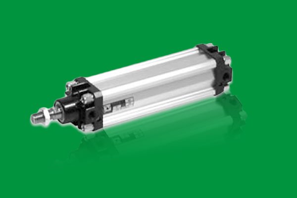
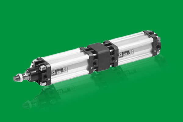
| SERIES 1319 - 1321 STANDARD CYLINDER ISO 6431 |
adapted to VDMA 24562 and CNOMO/AFNOR 49003 that guarantee the interchangeability of the cylinders
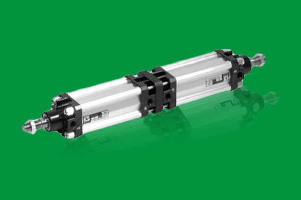
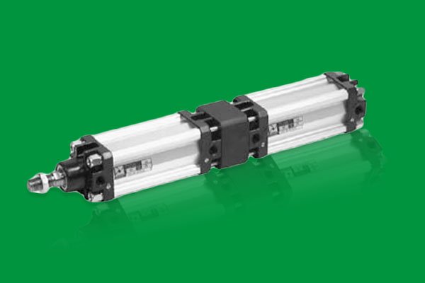
Ordering Code
1319.bore.stroke.stroke1.version magnetic piston , chromed rod
1320.bore.stroke.stroke1.version magnetic piston , stainless steel rod
1321.bore.stroke.stroke1.version non-magnetic piston , chromed rod
Bore(mm.) : 32 , 40 , 50 , 63 , 80 , 125
Stroke(mm.) : depend on request
Stroke1(for Tandem) (mm.) : depend on request


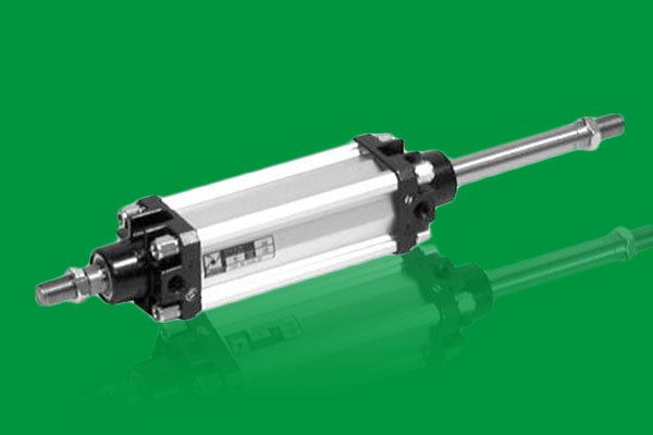
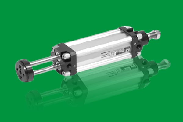
| SERIES 1325 - 1326 TWIN ROD CYLINDERS |
Type 1325 : with magnetic piston , chromed rod
Type 1326 : with non magnetic piston , chromed rod
Bore(mm.) : 32, 40 ,50 ,63 ,80 ,100 ,125
Stroke(mm.) : depend on request
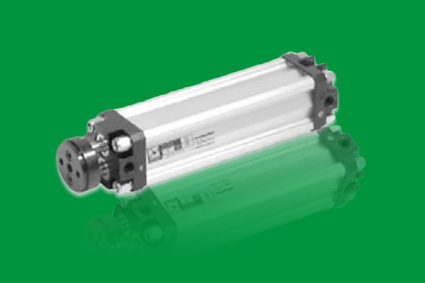
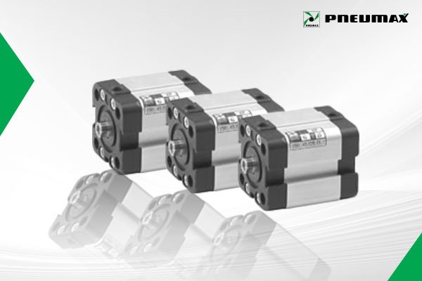
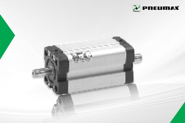
| SERIES 1500 EUROPE COMPACT CYLINDERS |
Type 1561 : standard ISO 6431 VDMA 24562.
: bore(mm) 32, 40 , 50 , 63 , 80 , 100
Type 1581 : standard UNITOP
: bore (mm) 20 , 32 , 40 , 50 , 63 , 80 , 100
Stroke(mm) : depend on request
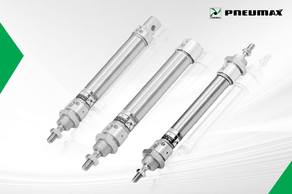
| SERIES 1260 - 1280 MICRO CYLINDER STANDARD ISO 6432 |
Microcylinders are the most widespread linear actuators in common use due to their reduced dimensions.
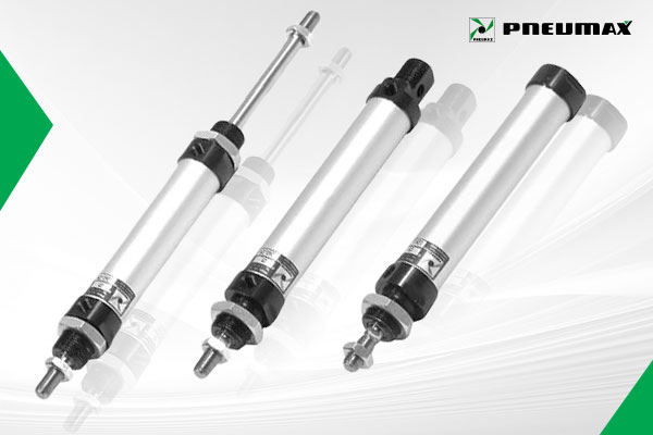
Type 1260 - 1262 Threaded end covers
hard anodized aluminum end covers and barrel
Option : Magnetic Piston
Bore(mm) 20 , 25 , 32 , 40 , 50
Type 1280 - 1282 Rolled end covers
hard aluminium end covers, rolled on the AISI 304 staainless steel barrel, magnetic piston and standard AISI 303 piston rod on all versions Bore(mm) 20, 25 , 32
| REED SWITCH / BRACKET |


Code 1320.B for cylinder bore 50 , 63
Code 1320.C for cylinder bore 80 , 100
Code 1320.D for cylinder bore 125
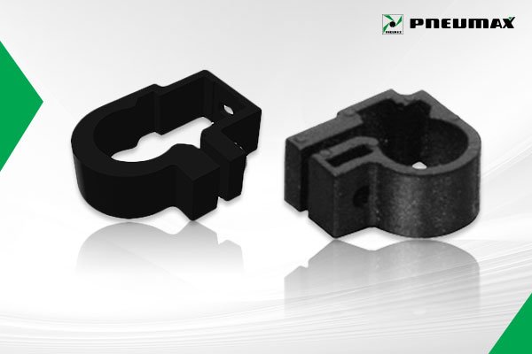
Sensor Brack ket for Micro cylinder
Sensor bracket 1260.Ø.F
Sensor bracket 1280.Ø.FS
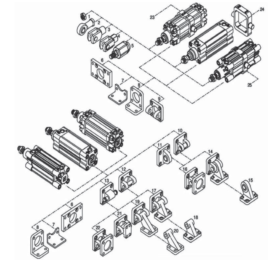
| CYLINDER MOUNTING FOR STANDARD CYLINDER |
| 1. Rod nut 2. Bail joint 3. Forks 4. Fork with clips 5. Self- aligning joint 6. Flange (MF1-MF2) 7. Short mounting foot brackets (in sheet metal MS1) 8. Standard mounting foot brackets 9. Front clevis 10. Rear Narrow clevis (AB6) 11. Rear male clevis (with jointed head according to DIN 648K standard) 12. Rear female clevis (MP2) | 13. Rear male clevis (MP4) 14. Complete square angle trunnion (pos.10 + pos.15) 15. Simple square counter clevis (pos.14) 16. Square angle trunnion with joined head (pos.10+pos.11) 17. Square angle trunnion (AB7) (pos.18+pos.12) 18. Simple square counter clevis (pos.17) 19. Simple rear trunnion with support brackets (pos.20+pos.12) 20. Simple square counter clevis (pos.19) 21. Standard trunnion 22. Standard complete 23. Intermediate trunnion |
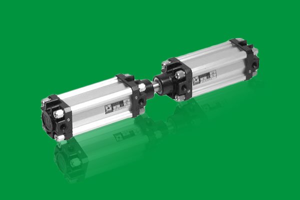
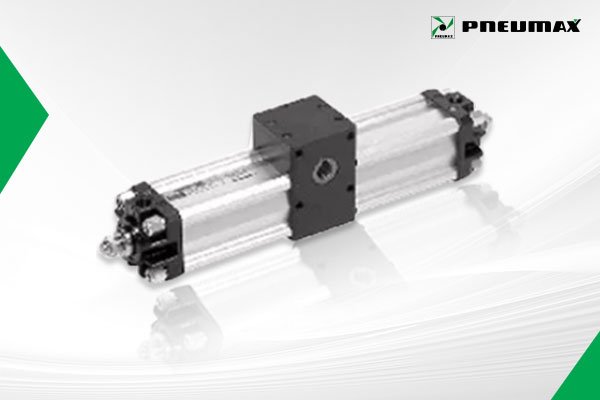
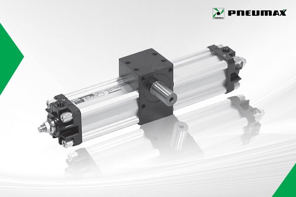
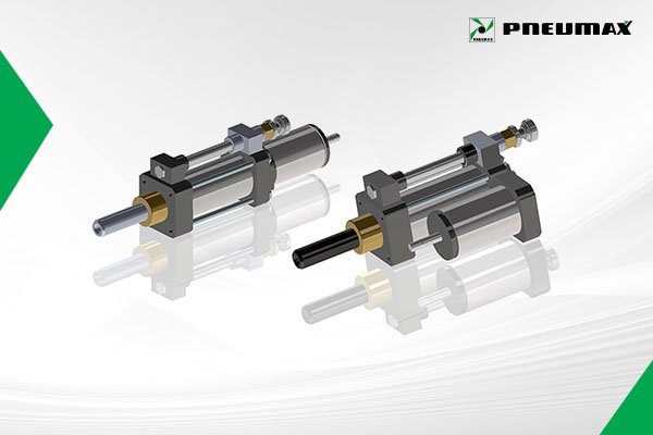
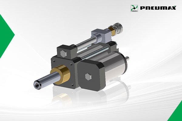
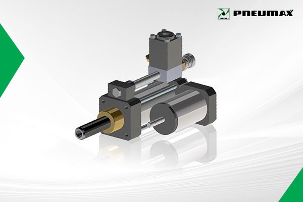
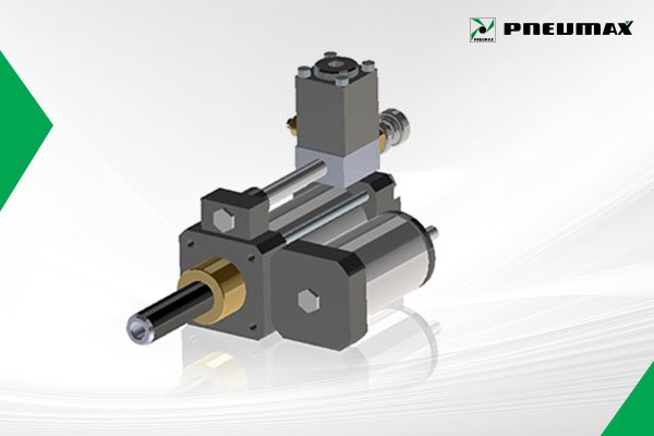
| SERIES 1330 - 1333 Rotary Actuator |
These rotary actuators transform the linear motion of a piston into the rotary motion of a shaft. The uses in automation are varying and always convenient compares with other solutions. Considering the bores from Ø 32 to Ø 100 and the wide range of rotary motion (from 1 degree to 360 degrees) it is possible to solve any problems one might have.
| Bore (mm.) : 32 , 40 , 50 , 63 , 80 , 100 Standard rotation 90 ํ - 180 ํ - 270 ํ - 360 ํ (+1 ํ) Rotating angle adjustment assy ±10 |
Female pinion version Ordering code
1330.Ø. * .01 magnetic
1331.Ø. * 01 non magnetic
1330.Ø. * 01R magnetic with rotating adjustment angle
1331.Ø. * 01R non magnetic with rotating adjustment angle * = rotating angle
Male pinion version Ordering code
1332.Ø. * .01 magnetic
1333.Ø. * .01 non magnetic
1332.Ø. * .01R magnetic with rotating adjustment angle
1333.Ø. * .01R non magnetic with rotating adjustment * = rotating angle
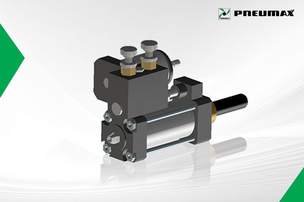
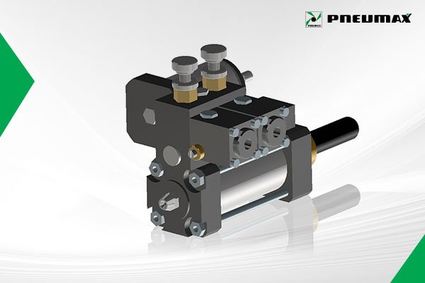
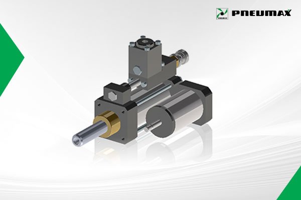
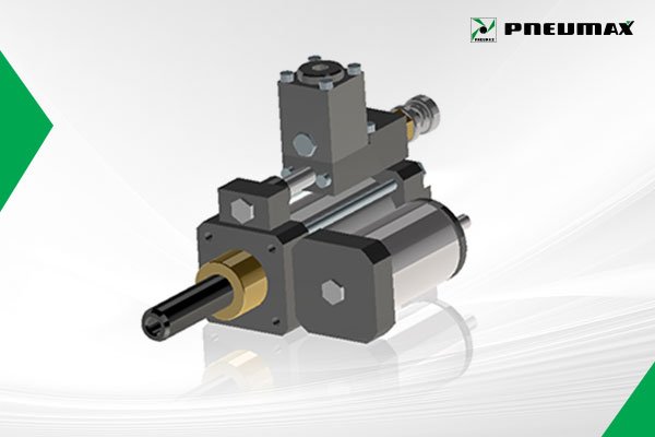
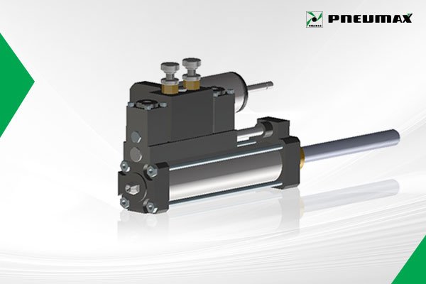
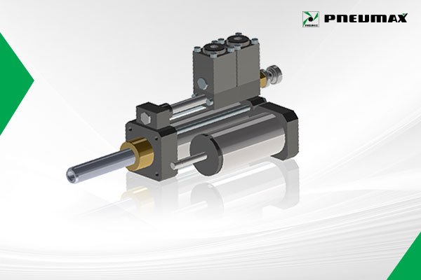
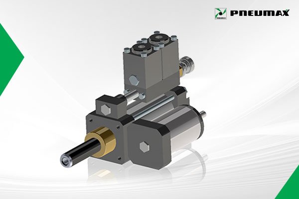
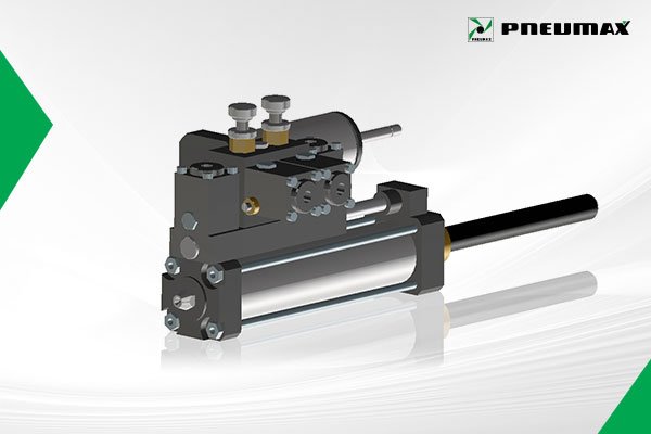
| SERIES 1400 HYDRAULIC SPEED CONTROL CHECK CYLINDER |
The hydraulic speed control check takes advantage of the incompressibility of oil which , going from the front chamber to the rear one(or vice versa) Through a flow regulator , absorbed and neutralizers the speed variation of the air cylinder. Such variations are proportional to the application loading.
Regulation on the outward stroke Tank in line / Lateral tank
1400.40.stroke.01.1
1400.Ø.stroke.01.2
Regulation on the inward stroke
1400.Ø.stroke.02.2
Regulation in both directions
1400.Ø.stroke.03.2
Regulation on the outward stroke with skip (Acceleration valve)
1400.40.stroke.01.04
Regulation on the inward stroke with skip (Acceleration valve)
1400.Ø.stroke.02.04
Regulation in both directions with skip (Acceleration Valves in both directions)
1400.Ø.stroke.03.04
Regulation on the outward stroke with stop (Stop valve)
1400.Ø.stroke.01.05
Regulation on the inward stroke with stop (Stop valve)
1400.Ø.stroke.02.05
Regulation in both directions with stop (Stop valves in both directions)
1400.Ø.stroke.03.05
Regulation on the outward stroke with skip and stop (Acceleration and stop valves)
1400.Ø.stroke.01.06
Regulation on the inward stroke with skip and stop (Accleration and stop valves)
1400.Ø.stroke.02.06
Regulation in both directions with skip and stop (Acceleration and stop valves in both directions)
1400.Ø.stroke.03.06
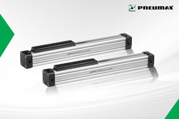
| SERIES 1605 RODLESS CYLINDER |
The purpose of producing a Rodless Cylinder is to provide space saving over conventional cylinders.
The barrel, made with extruded anodized aluminum, is formed with a longitudinal slot allowing the connection between piston and mounting carriage.
The pneumatic seal is obtained with the use of a hardened stainless steel band, located and retained along the slot with a magnetic field generated by two bands of plastoferrite.
Basic Version
Code : 1605.Ø.stroke.01.M
Single feed cylinder Left head
1605.Ø.stroke.02.M
Single feed cylinder Right head
1605.Ø.stroke.03.M
*Bore(mm) : 25,32,40,50,63
*Max. stroke 6 m.
Sensor brackets
Code : 1600.A
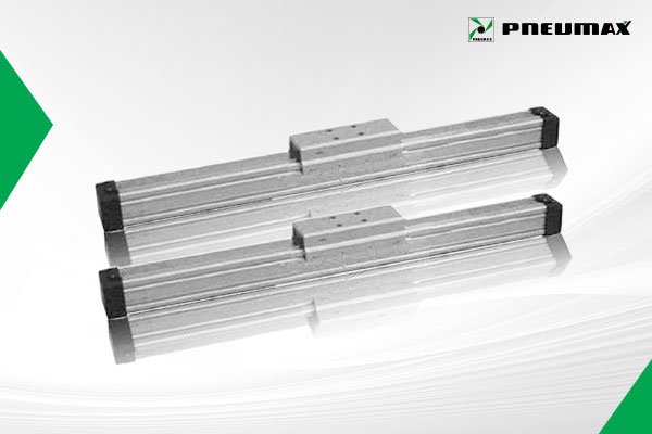
Code : 1605.Ø.stroke.01.MG
*Bore(mm) : 25,32,40
*Max.stroke 3 m.
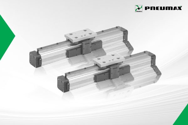
1605.Ø.corsa.01.MH Cylinder with sliding shoes guide
*Bore(mm) : 25,32,40
Code 1600.A.C sensor for alternating current with led
Code 1600.D.D sensor for continuous current with led
Code 1600.U universal sensor with led
Code 1600.U/1 universal sensor without led (REED ampulla only)