Setup and Functioning of Solenoid Control Valves
Last updated: 16 พ.ค. 2562 | 4605 จำนวนผู้เข้าชม |
Setup and Functioning of Solenoid Control Valves
Control valve, control armature, metering valve: the terms might be different – but it is the same product that they actually mean. In process-related practical use these components are usually called control valves, and the name refers to their function. They control and regulate the rate of flowing media (fluids). Control valves are operated in different ways: pneumatically, electromotorized, piezo-electrically and electro-magnetically.
The various drive principles essentially differ in price, size, type of media separation, dynamics and force properties.
Electro-magnetically activated control valves are called "solenoid control valves" or "proportional valves", which cover the orifice range below 12 mm (direct-acting valves) and 8-25 mm (servoassisted valves). Solenoid control valves are used as metering valves in closed control loops. The valve eliminates the difference here between the reference and actual value of the mapped process value (see fig. 1). However solenoid control valves – depending on valve type and application – are also used in open control loops in which the valve is operated without any feedback of the actual process value.
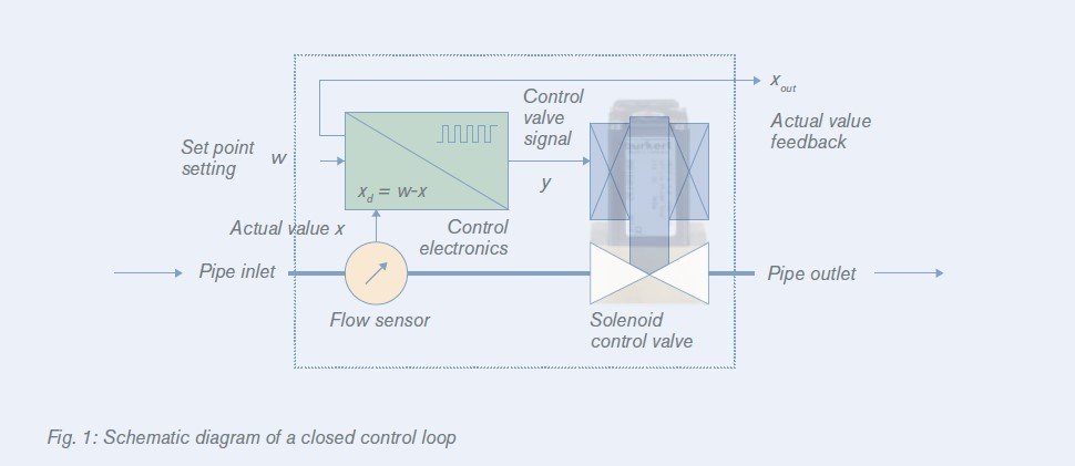
Solenoid shut-off valves are the basis for Bürkert solenoid control valves. Without electrical power
the spring forces the plunger directly on the valve seat. With that the valve is closed. Electrical current
through the solenoid (coil) causes a magnetism which lifts the plunger against the spring force.
The valve opens. With constructive changes in the solenoid shut-off valves, a balance between spring
and magnetic force can be produced for any coil current. The intensity of the coil current or the
magnetic power influences both the stroke of the plunger and the valve’s opening degree, whereby
valve opening (flow rate) and coil current (control signal) are ideally linear dependent on one
another (see fig. 2).
The flow direction in direct-acting solenoid control valves is typically from below seat. The medium
flowing in from below presses together with the generated magnetic force against the tension force
of the return spring, pressing from above. For this reason alone it makes sense to set the minimum
and maximum flow rate value of the working range (coil current) under operating conditions. Bürkert
solenoid control valves are closed without electrical power (NC, normally closed).
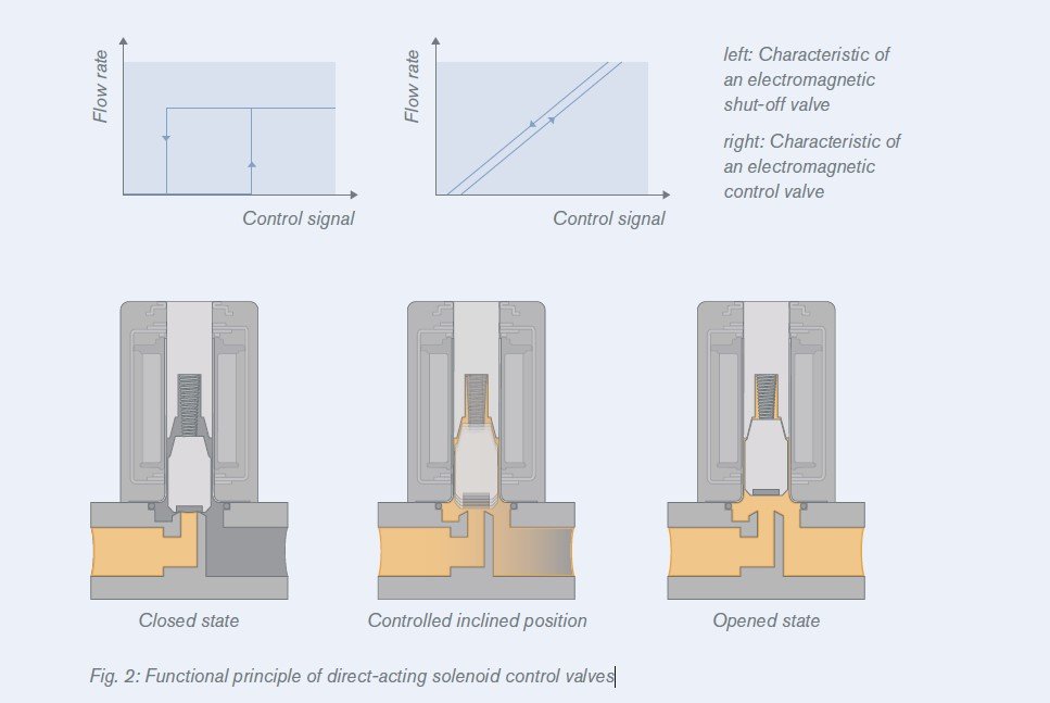
With an even geometry of the plunger and the plunger counterpart/stopper (flat stopper geometry) the
magnetic force drops too much with rising air gap making it impossible to use the valve as a control
valve. Equal balance states between spring and magnetic force at different values of the electrical
current can only be achieved with a specific design of both components. With the design of a conically
shaped area on the outside part of the stopper and a virtually mirror-inverted slant in the top part of
the plunger (see conical stopper geometry in fig. 3).
In the power off state the spring force alone closes the valve. A seal integrated in the bottom of the
plunger ensures that the fluid does not leak through the closed valve.
The plunger is guided precisely through the valve unit by a guide pin (top) and a flat spring (bottom) .
The more flexibly the plunger slides through the coil, the more pronounced the response sensitivity
and the more reproducible the control positions. This is because, in addition to the magnetic force
and spring force, a third unavoidable force, unwanted because of its consequences, enters the picture:
friction force. Friction disturbs the adjustment characteristic. It can, however, be significantly
reduced with a precise guiding of the plunger and special electronic controlling.
Controlling Solenoid Control Valves
In principle it is possible to control the proportional magnet with variable DC voltage, but static friction
can appear here on the plunger’s guide points. This impairs the sensitivity of the valve, and results
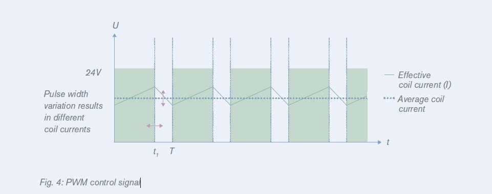
in greater hysteresis effects. To prevent static friction, the normal inlet signal is converted with a special control electronics – usually into a pulse width modulated voltage signal (PWM controlling, see
fig. 4). This kind of control puts the plunger into a very fast but weak amplitude oscillation. Despite, or
moreover because of the oscillation, the plunger’s balanced state is maintained, as is its constant
sliding friction. And the plunger’s oscillation motion has absolutely no effect on the fluid’s flow behaviour.
With PWM control the effective coil current with constant voltage supply is set via the duty cycle of
the rectangular signal. The PWM frequency is harmonized here on the one hand with its resonance
frequency and the damping of the spring-plunger-system, and on the other hand with the magnetic
circuit’s inductance. If the duty cycle t1/T (t1: power-on time, T: cycle duration, f=1/T: frequency) increases, the effective coil current “I” also increases, because the rectangular signal has also increased. If, however, the duty cycle falls, the effective coil current also falls.
Generally speaking: Small coils (e. g., type 2871) with low magnetic force react sensitively to higher
frequencies. With low frequencies these generate high motion amplitudes and an unnecessarily
high noise level. Big coils with a high magnetic force (e. g., type 2875), however, only result in dither
movements, and therefore sliding friction with low frequencies.


เนื้อหาที่เกี่ยวข้อง

Burkert Type 0330 Media-Separated Solenoid Valve
24 มี.ค. 2568
 คืออะไร ทำงานอย่างไร")

")